


Solutions
Horse Construction offers full range of structural strengthening materials with technical supports, documentation supports, products supports, project supports.
overpass reinforcement
1 The structure of the bridge
The Forehead Bay Overpass is located in the west ring section of the Central Ring Road in Wuhan and consists of a main bridge and a ramp (both are continuous beam bridges). This article mainly introduces the representative one-the second one on the main bridge up line (referred to as the upper two): the span is 2X16.172+3X25 m, the width of the carriageway is 16 m, and the one-way four-lane. The design standard is automobile super -20, the main beam concrete adopts CC 85 code 40 concrete, and the main reinforcement adopts rebar with a diameter of 25 mm.
1.1 Background of the bridge
Since it was opened to traffic in 2001, the road surface has been damaged seriously, and the owners often carry out repairs, but the poor road conditions cannot be fundamentally resolved. For some reasons, the overpass has not passed the completion acceptance.
1.2 Inspection before reinforcement
After the external inspection of the box girder, a large number of transverse cracks were found in the bottom plate and web of the box girder. Among them, cracks with a crack width greater than 0.20 mm accounted for 32.6% in number and 22.6% in length. The maximum crack width is 0.76 mm, and the crack depth is 4-7. 8 cm. The exterior of the box beam has local damage and tendons; there is water seepage at the fart part of the box beam, and the formwork of the box beam web and bottom plate is not completely removed.
There are some defects in the box girder, such as bar exposed, concrete peeling, unclean formwork removal, and water seepage. Some of the box girders are extremely heavy. A crack in the box girder was found inside the box girder; cracks with a width of not less than 0.2 mm accounted for 61.7% of the total number and 68.30% of the total length. The cracks inside the box girder are mainly concentrated on the web, and there are relatively few cracks on the top, bottom and diaphragms of the box girder, and the cracks are the main cause of the top plate.
2 Reliability of the bridge before reinforcement
1) According to the second-level requirements of the structure level, the reliable index of ductile failure: the mid-span and fulcrum section of the last three spans cannot meet this requirement, and the bridge must be reinforced from the aspect of bearing capacity.
2) Bridges with large spans have low reliability, and bridges with small spans have high reliability. This is the basis for the optimized design of carbon fiber reinforcement.
3 Bridge reinforcement measures
3. 1 General idea
1) Reinforce with the original design load, give due consideration to the requirements of the current code, and appropriately raise the standard, the requirements of Daliuge on the 1 Quzu Third Ring Road. Select a comprehensive reinforcement plan of pasting carbon fiber cloth, laying carbon fiber cloth under the main girder bottom plate and adding longitudinal steel bars in the bridge deck paving in the negative bending zone to improve the overall bending bearing capacity.
2) Without adding additional load to the structure, the bridge deck uses c50 waterproof concrete paving instead of the original paving (the original concrete paving has large areas of damage and other diseases). By planting the reinforcement and setting the shear force, the pavement layer and the box girder top plate can be firmly combined, which can not only allow the pavement layer to participate in the stress, improve the structural bearing capacity, but also significantly improve the overall rigidity of the structure.
3) Through the grouting treatment of the cracks, the cracked concrete is re-bonded into a whole, on the one hand, the bending rigidity and strength of the beam are improved. On the other hand, it can prevent moisture and air from entering the beam and improve the durability and impermeability of the bridge.
3.2 Treatment of cracks and local damage
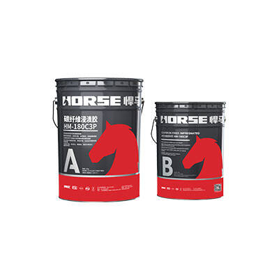
For cracks less than 0.1 mm wide, use crack repair glue for surface sealing treatment. For cracks larger than 0.1 mm wide, crack repair glue is used for pouring treatment. For areas where the cracks develop relatively wide, the fiber-baked cloth shall be pasted for reinforcement. The direction of the stressed fiber is required to be perpendicular to the crack, with a length of 0 5 m, symmetrically distributed on both sides of the crack. If it is the same as the position indicated in the design drawing where the cloth needs to be glued, a second layer of longitudinal carbon cloth needs to be glued on the bottom plate.
3.3 Carbon fiber reinforcement for box girder bottom plate
The first and second spans of the second upper row are within 1m from the centerline of the piers at both ends of each span in the longitudinal direction, and the corresponding side webs are 2m wide in the transverse direction. The second layer of carbon fiber cloth is longitudinally spaced from the centerline of the piers at both ends of each span by 3m, and the lateral webs are 1m wide and the middle webs 1.5m wide. Two layers of carbon fiber are pasted on the third to fifth spans of the seventh row of the main bridge, and the lateral extent is 2m on the corresponding side web and 3.75m on the middle web. The longitudinal first and second floors are respectively 1m and 3m away from the centerline of the piers at both ends of each span. The fiber direction is laid in the forward direction of the bridge, and the overlapping length of the carbon fiber cloth is required to be no less than 10 ctn when it is lengthened longitudinally. At the longitudinal end of the carbon fiber cloth, a toe cross bridge U-shaped hoop is set at a width of 0.5m, which is spread across the bottom plate and extends to the bottom of the box girder flange.
4 Reliability evaluation after reinforcement
After this reinforcement, all cross-sections of the bridge have met the requirements of the bending bearing capacity.
You can find anything here you are in need of, have a trust trying on these products, you will find the big difference after that.

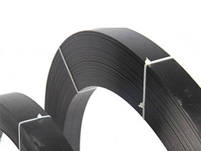
High strength carbon fiber reinforced polymer (CFRP) strip / laminate / plate for structural strengthening and concrete repair

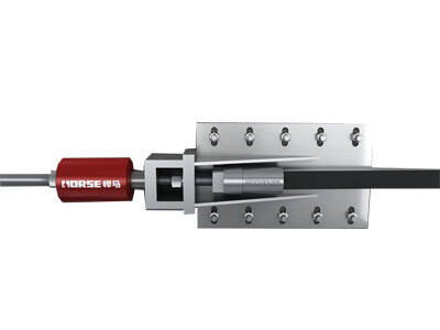
Prestressed carbon fiber reinforced polymer(CFRP) plate for slab, beam strengthening to increase stiffness, reduce distortion and deflection of members, reduce the cracks, avoid and stop cracking.

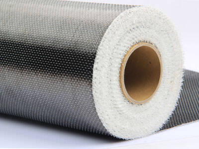
High strength, unidirectional carbon fiber sheet pre-saturated to form a carbon fiber reinforced polymer (CFRP) sheet used to strengthen structural concrete elements.
