


Solutions
Horse Construction offers full range of structural strengthening materials with technical supports, documentation supports, products supports, project supports.
Concrete Bridge Design Method---Prestressed Carbon Strip
Prestressed carbon fiber strip reinforcement technology is a new bridge reinforcement technology, its engineering application is not universal, and the system design method for typical concrete bridges is even lacking. This section will study the design methods of concrete girder bridges with four cross-sectional forms: hollow slab girder, T-beam, combined small box girder, and box girder. In-depth research has been done in three aspects: the layout of prestressed carbon fiber slats in the transverse direction, the layout of prestressed carbon fiber slats in the longitudinal direction, and the structural design of anchoring devices.
1 Hollow slab beam reinforcement design
Hollow slab girder is one of the most commonly used bridge cross-section forms, mainly used in simply supported beam systems. The simple-supported slab beam is hollowed out in the middle to reduce the structural weight, and the material is relatively economical, and it is suitable for prefabricated assembly. In addition to reinforced concrete hollow slab beams, prestressed concrete hollow slab beams are often used at present. Although there are many hollow slab sections in the middle, the thickness of the hollow slab bottom strip is about 10cm, which is relatively thin. In the process of strengthening the prestressed carbon fiber strip, a 5cm wide prestressed carbon fiber strip is generally used, and the tensile tonnage is not very large. When strengthening the prestressed carbon fiber strip, the design is mainly carried out from the aspects of the transverse bridge direction, the longitudinal bridge direction, and the structure of the anchoring device.
(1) Horizontal bridge design
The veneer width of the hollow slab girder bridge is generally about 1m-1.5m, and the beam height is generally below lm. Because the slab girder bridge is weaker in concrete strength than the box girder bridge, the tensile tonnage is relatively low. When arranging the horizontal bridge, generally 1 to 2 anchor systems are arranged on the bottom strip, and the width of the prestressed carbon fiber strip is 5 cm. The ideal horizontal bridge layout is shown in the figure

strip beam cross-bridge design-prestressed carbon strip
Anchor bolts are drilled and anchored at the bottom of the hollow slab, and anchoring devices are installed. The specific positions and detailed dimensions need to be partially checked and passed.
(2) Longitudinal bridge design
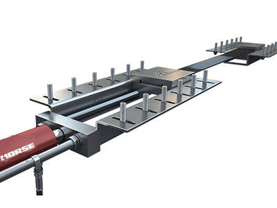
When designing the longitudinal bridge direction of the hollow slab girder, the tension end and the anchoring end should be as close as possible to the support position, but at the same time, the construction space needs should be considered, and the support should not be too close. Because the anchoring system is arranged side by side, the tension ends should be set on the same side. The ideal longitudinal bridge layout is shown in the figure

Longitudinal Bridge Design of strip Girder-Prestressed Carbon strip
As shown in the figure above, a 1.4mm thick, 5cm wide, L+0.55m long carbon fiber strip is used in the span of the bridge, and a working length of 0.5m is considered (L is the distance between the tension end and the anchor end). Each slab beam is longitudinally arranged with carbon fiber strips along the slab beam bottom strip, and 1-2 strips are arranged side by side in the horizontal direction. The anchoring end and the tensioning end should be arranged side by side, the anchoring end is lm away from the centerline of the support, and the tensioning end is 2m away from the centerline of the support.
2 T beam reinforcement design
At present, the T-shaped cross-section is the most commonly used type of assembled rib beam cross-section for main beams in my country. T-beam has its own characteristics. The wing strip can be used as the carriageway slab of the bridge as well as the main compression flange. For the prestressed structure, the tension flange part is designed into a widened horseshoe shape, which is conducive to the arrangement of the prestressed steel strands and the pre-compression stress of the steel strands. At the same time, the T-beam is simple in appearance and convenient to manufacture. It is connected by transverse beams, and the integrity is also good. Because the horseshoe area of the T beam is limited, in the process of prestressed carbon fiber strip reinforcement, generally 5cm wide prestressed carbon fiber strip is used, and the tensile tonnage will not be very large. When strengthening the prestressed carbon fiber strip, the design is mainly carried out from the aspects of the transverse bridge direction, the longitudinal bridge direction, and the structure of the anchoring device.
(1) Cross-bridge design
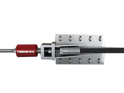
Due to the limited area of the T-beam horseshoe, in the design of the cross bridge, an anchor system is generally arranged on the bottom of the web. Due to the small width of the web, a U-shaped anchoring device can be used in the design. When the tension tonnage is large, two anchor systems can be added under the T-beam web. Drill holes can be drilled to plant high-strength anchor bolts or drill through the web to pull anchor rods, as shown in the figure. For prestressed concrete T-beams, you must avoid touching the bellows during the drilling process.

T-beam cross-bridge design--prestressed carbon strip
(2) Longitudinal bridge design
When designing the longitudinal direction of the T-beam, the tension end and anchor end should be as close as possible to the position of the support, but at the same time, the construction space needs should be considered, and it should not be too close to the support. The anchoring system adopts a staggered arrangement, and the tension end should be spaced a certain distance. The ideal longitudinal bridge layout is shown in the figure

T beam longitudinal bridge design--prestressed carbon strip
As shown in the figure above, a 1.4mm thick, 5cm wide, and L+lm carbon fiber strip is used in the span of the bridge, considering the working length of lm (L is the distance between the tension end and the anchor end). Each T-beam is arranged with carbon fiber strips along the longitudinal direction of the horseshoe, with one on the bottom edge and two on both sides of the web. Anchor ends and tension ends should be arranged in a staggered manner to ensure that the construction does not affect each other. The anchor ends are away from the centerline of the support by lm, and the tension ends are 2m away from the centerline of the support.
3 Reinforcement design of combined small box girder
The combined small box girder is a prefabricated bridge type, which is convenient and quick to construct, and has been used more in my country in recent years. Each small box girder is combined through cast-in-place sections and is often used in the construction of simply supported variable continuous bridges. This kind of combined small box girder structure is generally used for bridges with a span greater than 20m, generally prestressed concrete bridges. When strengthening the prestressed carbon fiber strip, the design is mainly carried out from the aspects of the transverse bridge direction, the longitudinal bridge direction, and the structure of the anchoring device.
(1) Cross-bridge design
The thickness of the bottom strip of the combined small box girder is generally greater than 18cm. In the case of determining the tensile tonnage, a 5cm wide carbon fiber sheet is used. A piece of small box girder is generally arranged with 2 to 3 anchor systems in the transverse direction. The anchor is anchored at the bottom of the small box girder to drill and plant anchor bolts. Try to locate the anchoring device on the variable thickness section of the bottom strip, and avoid touching the corrugated pipe during the drilling process. The ideal horizontal bridge layout is shown in the figure

Transverse Bridge Design of Combined Small Box Girder--Prestressed Carbon strip
(2) Longitudinal bridge design
When designing the longitudinal bridge direction of the combined small box girder, the tensile end and the anchoring end should be as close as possible to the position of the support, and the anchoring device should be positioned as far as possible in the variable thickness section of the bottom strip. But at the same time, the construction space needs should be considered, and it should not be too close to the support. The anchoring system adopts a staggered arrangement, and the tension end should be spaced a certain distance. The ideal longitudinal bridge layout is shown in the figure

Longitudinal Bridge Design of Combined Small Box Girder--Prestressed Carbon strip
As shown in the figure above, a 1.4mm thick, 5cm wide, L+1m carbon fiber strip is used in the span of the bridge, taking into account the working length of lm (L is the distance between the tension end and the anchor end). Each small box girder is arranged with 2 to 3 carbon fiber strips in the longitudinal direction of the bottom strip. When arranging three carbon fiber strips, the anchoring end and the tensioning end should be arranged staggered to ensure that the construction does not affect each other. The anchoring end is 1m away from the support centerline, and the tensioning end is 2m away from the support centerline.
Concrete Bridge Design Method---Prestressed Carbon Strip(2)
You can find anything here you are in need of, have a trust trying on these products, you will find the big difference after that.

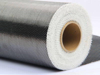
Prestressed carbon fiber reinforced polymer(CFRP) plate for slab, beam strengthening to increase stiffness, reduce distortion and deflection of members, reduce the cracks, avoid and stop cracking.

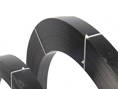
Prestressed carbon fiber reinforced polymer(CFRP) strip for slab, beam strengthening to increase stiffness, reduce distortion and deflection of members, reduce the cracks, avoid and stop cracking.

Prestressed carbon fiber reinforced polymer(CFRP) laminate for slab, beam strengthening to increase stiffness, reduce distortion and deflection of members, reduce the cracks, avoid and stop cracking.
